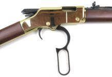
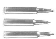
In 1894, Arthur William Savage set up the Savage Arms Company in Utica, New York. After stints managing a coffee plant in Jamaica, designing torpedoes for the Brazilian Navy, and as a superintendent for the Utica Belt Railroad, Mr. Savage sat down to compile his design ideas for a lever-action rifle.
In 1893, Savage patented the first truly hammerless lever-action rifle. This streamlined rifle differed from the Winchester and Marlin lever-action rifles of the same era in that it used a rotary magazine that allowed the use of ballistically superior pointed-nose bullets. All of the other lever-actions of this period used a tubular magazine. The tubular magazine meant that cartridges were fed into the tube with bullet nose to primer, necessitating the use of blunt-nosed bullets to avoid a chain-fire situation.
By 1895, Savage’s rifle was in full production as the Model 95. Around 1899, a few small design improvements were made and, since then, the design has remained relatively the same—one of the “bread and butter” firearms of this company.
Sooner or later, one of these rifles will cross your bench. It makes some people shudder to think of restoring one of these older rifles by means of re-bluing or stock refinishing. If you have any thoughts of maintaining collectability, keep in mind that the firearm is more desirable to a collector with whatever original finish remains on the wood and metal—even if there is only 20 percent of the original finish remaining.
Whenever a firearm with collectible value is brought into my shop for restoration, I make it a policy to inform the owner that refinishing will diminish its value to a collector. In the case of the rifle detailed here, however, collectible value was not an issue. The rifle had been previously drilled and tapped for scope bases; sling swivel studs had been installed; and, at one point in time, the stock had been replaced. This rifle had been passed down to the present owner who had no intention of selling it, for now, and his plan was to use it as a hunting gun.
American Gunsmith Book of the Rifle
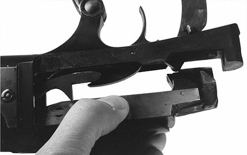
Disassembling the Savage 1899
For a thorough cleaning or for re-bluing, the rifle must be taken down completely. The first step, as always, is to make absolutely sure the firearm is devoid of ammunition in the chamber and the magazine. Remove the buttplate to reveal a hole in the stock for the through-bolt attaching the stock to the receiver. Removing the through-bolt will allow removal of the stock from the receiver. The forearm has one screw going through the forearm and into a stud dovetailed into the bottom of the barrel.
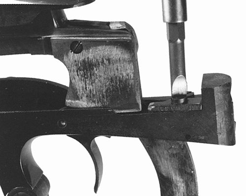
Once the stock has been removed, all the internal parts operating the firing sequence will be accessible. The bolt stop is on the inside top of the bottom action tang. This part keeps the lever from moving the bolt too far to the rear and allowing the bolt to disengage from the receiver raceways guiding it. Remove the screw retaining the bolt stop with a #240-4 magna-tip screwdriver bit. The forward portion of the bolt stop is usually found to be slightly rounded over from battering by the rear of the bolt body. It doesn’t hurt to leave it this way, but if you feel better filing off the rollover burrs, then by all means do so.
American Gunsmith Book of the Rifle
Next push the lever forward as far as it will go. This pushes the bolt to the rear. Tilt the bolt body slightly away from the lever and then the bolt body can be removed out the rear of the receiver. Set the bolt body aside for later attention.
Remove the finger-lever screw with a #360-4 bit, and push out the threaded screw sleeve to the right side with a 1/8-inch punch. Note the little nub at the outside diameter of this sleeve; it must be aligned with the cutout in the lever when reassembling.
The trigger-return spring is made from flat spring stock, and can be removed by backing out the screw holding it in place using a #240-3 magna-tip bit. The trigger-pivot pin can be drifted out using a 1/8-inch punch drifting the pin from left to right. Push the trigger upward and then away from the stud on the sear to disengage it from the slot.
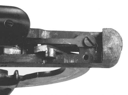
On the right side bottom of the lower tang is the lever lock. This slides forward and backward. When in the forward position, the lever is locked in place and the trigger is blocked. When pushed back, the rifle is ready for firing, ejecting the empty case, and then charging the chamber with a fresh round. To remove the lever lock from the receiver, drift out the retaining pin from left to right with a 3/32-inch punch.
At the top center of the upper tang protrudes a 1/8-inch-diameter indicator notifying the operator when the striker is retracted and ready to fire. A crosspin holds the cocking indicator in place, and can be drifted out with a 1/16-inch punch. The trigger will now come out the bottom of the receiver.
American Gunsmith Book of the Rifle
Savage 1899 Magazine Disassembly
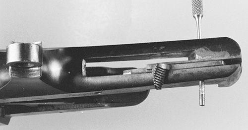
As you know, taking things apart is pretty easy if you have the right tools. To remove the sear, you need to alter a standard magna-tip bit into a spanner-type bit. This modified bit is not intended to be a screw-turning tool. It is used to hold the slotted nut stationary while the screw is backed out. Alteration can be accomplished with a shafted stone dressed to 0.187-inch diameter in your Moto-tool. Grind the center of the blade on a #300-4 magna-tip bit to a slight radius that will clear the off-side end of the screw. Place this altered bit into the slotted nut, and hold the nut stationary while backing the slotted screw out of the receiver with a #300-3 magna-tip bit. The sear can now be removed (out the rear of the receiver) along with the cartridge guide located in the left side of the receiver.
The most unique aspect of this rifle is the design of the rotary magazine, but without some precautions, the rotary magazine can be a nightmare to reassemble. Assuming that the loaded-round indicator, visible through the small window in the left side of the receiver, reads correctly, I place a small witness mark in the receiver and one on the carrier-spindle head. These two marks are tiny and are used for alignment when the time comes for reassembly.
The screw on the left side of the receiver above and to the left of the cartridge-counter window is really a threaded-end pin that holds the front of the rotary magazine spindle in place. Remove this threaded-end pin with a #150-3 magna-tip bit. When this pin is completely withdrawn from the receiver, the front of the steel magazine spindle will unwind under the tension of the spring inside the brass cartridge follower. This is the reason the witness marks are dimpled in place before this pin is removed. The rotary magazine assembly can now be removed out the front of the receiver.
The cartridge guide is located on the right side of the receiver, and is normally not removed during takedown and cleaning. If re-bluing is in order, the two retention pins are drifted downward into the receiver with a 5/64-inch punch. Remove the cartridge guide to the left and retrieve the two retention pins which will now be resting in the bottom of the receiver.
This particular rifle came into my shop for a complete restoration, so I had to separate the steel spindle from the brass rotary magazine follower for bluing. The same spanner bit that was used to hold the sear-nut screw for removal can be used for the separation of these two parts. A note of caution: The spanner nut at the front of the rotary magazine assembly is a left-hand thread. This nut must be removed in a clockwise direction or you will either ruin the nut or the spanner bit and possibly damage the threaded shaft going through the brass follower.
Clamp the rear end of the steel spindle in a vise, and then remove the slotted nut in a clockwise direction—as though tightening an ordinary screw. Notice that the coil spring going around the shaft of the spindle has a straight tail at each end. Observe how this fits into the small hole for it to activate the rotary cartridge follower. To clean the brass follower and shine it up a bit, I just tossed it into my cartridge-case polishing tumbler and ran it for 24 hours. The follower came out nice and shiny and was then cleaned with alcohol to remove the polishing rouge. If a cartridge-case tumbler is unavailable, the brass follower can be polished with a soft-bristled toothbrush and a nonabrasive product such as FLITZ. The stamped numbers on the front outside diameter of the follower can then be highlighted with a black lacquer paint stick to make them more visible to the rifle’s owner.
American Gunsmith Book of the Rifle
Bolt Components of the 1899
The bolt assembly on the Savage Model 1899 is a simple system. The striker or firing pin has a tail on the rear that engages the sear as the lever is moved forward. Once the trigger is pulled, the sear drops down allowing the striker to travel forward into the primer of the cartridge case. This is truly a hammerless action.
To remove the firing pin, the firing-pin retention screw/pin must be removed on the left side of the breech bolt. This screw/pin is staked at the edges of the screw slot, so expect some resistance when removing this screw. A #150-1 magna-tip bit fits this slot perfectly. Watch for the small firing-pin return spring to drop out once the firing pin is removed. This is a small coil spring that could easily get lost if you didn’t know it was there. The forward end of the striker is pinned in place with a retention pin. If the tip has broken off and needs replacement, the retention pin can be drifted out with a 5/64-inch punch. The extractor runs about three-quarters of the way along the right side of the bolt. For removal, the top of the bolt is placed down on a bench block with the pin retaining the extractor located over one of the holes in the bench block. Using a 0.072-inch punch, drift the extractor pin down and out of the bolt body.
About the only way to get a smoother trigger pull on this rifle is to polish the mating surfaces of the sear face and the engaging striker face. The idea here is to maintain squareness of these faces and to not remove an excessive amount of metal. Neither of these parts should be shortened in height. Start out with 320-grit emery paper backed by a square solid sanding block, and progress through 1200-grit to get a smooth, square surface on these mating parts. When reassembled, a graphite-based grease or a product like Brownells Action Magic II will slick things up quite nicely.
Reassembly Tips
When reassembling the striker into the bolt body, remember to insert the little return spring just before the striker is pushed all the way forward. The lever-pivot bushing holding the lever-retention screw has a small lug that must be mated to the recess in the right ear of the lever. A dab of thread sealer will keep the screw in place after reassembly. Be sure to clean the threads with a solvent before applying the thread sealer.
When reassembling the magazine components, remember that the screw on the front of the carrier spindle is a left-hand thread and, to tighten it, you must turn it counterclockwise.
If witness marks were not placed prior to disassembly, the spindle head must be tensioned so that the counter numbers are correct, and the crosspin lines up with a slot in the spindle head. The loaded round indicator should read zero.


