18 years of age, John Mahlon Marlin began his working career with American Machine Works. He was paid nothing for his first six months of labor, and for the following six months he was paid the princely sum of $1.50 per week. By the end of John’s three-year apprenticeship, his weekly wage had grown to $4. (What would a guy would do with all that money?) It’s rumored that Mr. Marlin then went to work for Colt Firearms as a machinist and toolmaker until his departure and move to New Haven around 1863.
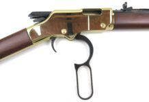
The local directory of the time listed Mr. Marlin as a pistolmaker, though his first patent, dated 1879, was for a lever-action rifle. Now, almost 120 years later, the Marlin Arms Company is synonymous with the lever-action rifle, and it’s almost impossible to skulk through an Eastern deer woods without encountering a hunter carrying a lever-action rifle of their make.
The Marlin 336 is famous for the myriad of suffixes added to the model number and stamped along the left side of the barrel. The most notable addition to the model number occurred in 1988, when the company began adding an “S” to all suffixes. The “S” denotes the addition of a crossbolt safety that prevents the hammer from traveling forward and striking the firing pin in the event the operator’s thumb should slip off during cocking.
Basic take-down of all the Model 336s is the same, so the following instructions will get you through whatever suffix may be stamped on your rifle or carbine. These instructions can also be applied to the dressed-down versions produced by Marlin as the Models 30 and 36 with all same accompanying suffixes.
As always, the first step in disassembling any firearm is to ensure that the chamber and magazine are empty of any ammunition or obstructions.
Removing the Stock and Forearm
Clamp the receiver in your padded-jaw vise. Remove the tang screw going through the upper receiver tang with a #300-5 Magna-tip bit, and slide the stock off to the rear. If the stock is stubborn, a whack or two with a rubber-face dead-blow hammer at the front of the comb will usually do the trick.
On both sides of the metal forearm endcap are screws that enter a hanger that’s dovetailed into the bottom of the barrel. These screws are removed with a #180-3 Magna-tip bit. The magazine end cap is then removed with the same bit as that used for the forearm endcap.
Now slowly relax the tension on the magazine follower spring. Tilt the front end of the magazine tube down and away from the stud that anchors the magazine tube, while pulling the forearm and magazine tube forward and off the barrel.
Look over the rear mouth of the magazine tube for any unevenness or burrs that will scratch the brass cartridge case. I like to put a very slight chamfer on the inside edge of the magazine tube, and then polish the chamfer.
Disassembling the Internal Action Parts
With the stock removed, the hammer spring is now accessible. Clamp the barrel tightly in the padded-jaw vise with the top of the receiver up, and see that the hammer is forward and the lever is closed. (We don’t want to have any tension on the hammer spring.) Working from the left side of the receiver, push the hammer spring adjusting plate to the right, disengaging the bottom of the adjusting plate from the groove in the bottom of the tang. This can be done with the thumb of the right hand. Watch that the hammer spring doesn’t get away.
Push the finger lever down so that the bolt is retracted out the back of the receiver about an inch or so. Remove the finger lever screw with a #270-3 Magna-tip bit, and then simply pull on the back end of the bolt while pulling the finger lever down and away from the receiver. Pull the bolt fully backward and out the rear of the receiver. Set the bolt aside for attention later.
Now turn the barreled action in your vise so that the bottom of the receiver faces up. Remove the screw at the front bottom of the receiver with a #240-3 Magna-tip bit. On the right side of the receiver, just above the hammer pivot screw, remove the carrier pivot screw with a #180-2 Magna-tip bit. On the left side of the receiver, above the ears for the finger lever, is the last screw to be removed before the bottom tang can be detached. This screw is removed with a #270-2 Magna-tip bit. Pull the bottom tang down and out of the receiver. Set this subassembly aside for later attention. The hammer pivot screw can now be removed with a #240-4 Magna-tip bit.
The cartridge carrier should be loose in the receiver, and can now be lifted up and out of the receiver along with the breech block. Also, look for the ejector to drop out of its place in the left receiver wall. Look over the ejector to see that this part is in good shape and that it hasn’t been ground on or worn to the point of failure. The small flat spring is replaceable if it has broken, or both parts can be purchased as a unit if so desired. Breakage is not common with these parts, but it pays to stock one or two for an owner who might lose one when disassembling his firearm.
About 11/2 inches to the rear of the loading gate cutout is the screw that keeps the loading gate in place. This screw is removed with a #150-3 Magna-tip bit. This screw has a tendency to loosen up and cause havoc with the loading operation of the rifle. To prevent future loosening, it’s a good idea to clean the threads on the screw and in the tail of the loading gate, and place a drop of thread sealer on them during assembly.
Check the front edge of the loading gate for any roughness or burrs. Burrs will cut the outside diameter of a cartridge case. Look over the inside edge of the front of the loading gate window in the receiver for any burrs there also. To prevent brass shavings from collecting in the internal workings of the action, any burrs in these areas should be removed and these areas polished. This polishing can be done by whatever means you prefer, emery paper or moto-tool. Use care to not remove an excessive amount of material; we just want to smooth any rough edges.
Now that all the parts have been removed, you’ll probably notice an accumulation of brass dust in the receiver. In addition to the sharp edges on the front of the loading gate and the loading window in the receiver, the cartridge access hole in the receiver is also a likely area to shave brass. This oblong-shaped hole is located just below the barrel. By carefully inspecting the leading edge of this guide hole going into the magazine tube, you will see any burrs that may be present. Carefully remove all the sharp edges and polish this area to at least a 600-grit finish. This polishing will help cartridges find their way in and out of the magazine tube more easily, and prevent most if not all of the brass dust accumulation in the receiver.
While you’re at it, check the magazine spring for any kinks or rust pits that will affect the performance of this spring. Clean out the internal surface of the magazine tube with an old .410 bore brush wrapped with #0000 steel wool and dipped in solvent. Then dry out the tube thoroughly with several patches.
Sub-Assemblies
The finger lever has one important part that should be checked for excessive wear. The finger lever plunger retaining pin can be removed by drifting with a 0.050-inch punch. Once the punch is removed from the cross hole, watch for the plunger spring to come out quickly. Look at the area on the plunger where the two angles intersect to see if it has become excessively worn. This point should be fairly sharp. If it has gotten overly rounded, it’s time for a new one. Clean out the recess in the finger lever and place a small dab of a graphite-based grease in the hole to ensure smooth movement of the plunger.
The bottom tang contains three parts that usually don’t wear out, but will need to be removed if re-bluing is required. The trigger pivot pin captures both the trigger and sear, and can be removed by drifting out the pivot pin with a 3/32-inch punch.
On the side of the bottom tang, directly to the rear of the trigger pivot pin, is the safety block pivot pin. This pin can be drifted out with a 0.050-inch punch. Look over the trigger safety block spring to see that it is not deformed. Check the trigger and sear to see that there are good sharp angles and corners present, and that the edges are not chipped or broken.
On the bolt body, we find two major parts that require inspection. The extractor fits on the outside of the bolt, and is formed from flat spring steel. The extractor hook rarely breaks, but, in the event that it does, the extractor is easily replaced by prying the old extractor off and snapping a new one on. When replacing an extractor, check to see that the top and bottom outside edges are not dragging on the inside of the receiver as the bolt is moved forward and backward. A dressing with a fine-cut file will remove any high spots on the extractor if drag is present.
When a firing pin fails, it is almost always the tip that walks off the job. To remove the two-piece firing pin, drift out the crosspin located on the top of the bolt at the right rear with a 1/8-inch punch. There is a small flat spring that works to tilt the rear firing pin piece downward when in a relaxed state. This is by design, as the rear section is pushed up into place by the locking bolt when the bolt is levered forward.
The bolt body has a satin-chrome plating applied as a deterrent to wear, but, if burrs are detected anywhere on the bolt body, they can be easily removed with a smooth-cut file.


