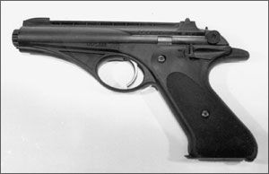
During World War II, Robert L. Hillberg worked for Republic Aviation, the manufacturer of the P-47 Thunderbolt. A fighter-bomber nicknamed “Jug” by its pilots, the rugged plane could take quite a pounding and still return safely to base. The P-47 packed eight Browning 50-caliber machine guns, four mounted on each side of its somewhat elliptical wing.
Hillberg was given the responsibility for fitting the big guns plus their ammo into the limited space available. He learned a great deal about lightweight aluminum alloys in the process. When he left
300
Republic after the war, he joined High Standard Manufacturing as head of research and development. Shortly thereafter, High Standard became the first firearm company to employ aluminum alloys commercially.
When he left in 1953 he linked up with a tool company and initiated work on a pistol of his own design. Among his goals were the capping of manufacturing costs by assembling working parts outside the gun, slipping those assemblies into its aluminum-alloy frame, giving the pistol a racy appearance, and competing with Ruger and High Standard models selling at the time for $39.95. (Them days is gone forever, right?)
Hillberg was well aware of Eli Whitney’s contributions to the making of firearms. In that great inventor’s honor, he and the backers he’d assembled voted to name their new company Whitney Firearms, Inc. Hillberg was also a big football fan. His favorite team was fielded by the University of Michigan. What happened next seems almost predictable: The Whitney Wolverine was introduced to the public in 1956.
Prior to the debut, an exclusive contract was signed with a New York distributor for a minimum of 10,000 Wolverine pistols a year. As it turned out, the distributor over-estimated the sales potential, and didn’t want any more pistols added to its existing stock, despite the fact that the factory was already set up to produce them. To avoid bankruptcy, Hillberg and his principals approached another party to purchase the name Whitney Firearms, along with all remaining inventory including parts. The new owner started shipments right after the deal went through in 1957. He was stopped abruptly by a lawsuit filed by the New York distributor which claimed its contract prohibited anyone else from making the pistol. I’m no legal scholar, but it seems to me that by failing to purchase a minimum of 10,000 pistols, the distributor’s lawsuit should have been dismissed. It was not, however, and Whitney production came to an end in 1959.
I’m not alone in believing the pistol died too soon. Way too soon. Obviously agreeing with me is the present management of Olympic Arms; they’re now producing an exact copy of the Whitney that would make its inventor proud. He might be mildly curious why they didn’t go all the way and stamp “Wolverine” on its side. Do you suppose it might be because Olympic is based in Olympia, Washington, and worried about offending University of Washington football fans?Field Stripping the Whitney
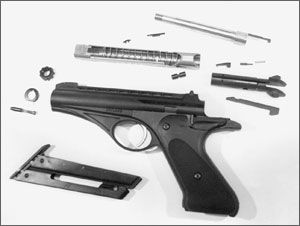
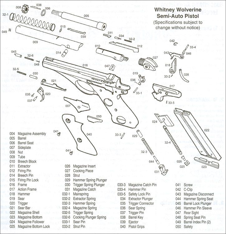
The tube (#009) of a Whitney serves the same purpose as the slide in other semi-autos by housing the barrel, recoil spring, and breech-bolt assembly. It has no bushing.
The barrel-locking plunger (#045) is located in the front of the frame beneath the barrel nut (#008). Depress the plunger and unscrew the nut counter clockwise until it clears the barrel. Now cock the hammer, grasp the cocking piece (#027), and pull the tube assembly
300
out to the rear. Remove the barrel key (#038) and barrel seat (#006) from the front of the frame. After you pick the firing-pin lock (#015) from the top of the tube, you can pull out the firing pin (#012). If it hesitates, bump the rear of the cocking piece on your bench. Use the firing pin to push out the breech pin (#014) by pulling the barrel slightly forward and holding it there as you push. The breech block (#010) and barrel (#005) are now free and can be taken from the tube.
The ejector (#039) is press fit to the barrel. Unless it’s broken, leave it alone. When and if it must be replaced, be careful not to bend the part while getting it out or getting a new one installed. The extractor (#011) is a three-piece affair including a plunger (#034) and spring (#32-2) lodged in the right side of the breech bolt as you look down on it. A blunted scribe or other small tool is used to depress the rear of the extractor. The spring will push the plunger forward, and probably the extractor along with it, as soon as you remove the tool.
In effect, when you field strip a Whitney, you detail strip its entire upper. What is spread out on your parts mat will resemble no other pistol you’ve worked with.Detail Stripping the Frames
For the sake of clarity, I will refer to the frame (#016) as the “main frame” and use Olympic Arm’s nomenclature for the action frame (#017).
The hammer is eased into its fully forward (fired) position. Remove the grips with a Torx bit or driver. Under the left grip, you’ll immediately see the sideplate (#007) and safety (#050). There’s no need to dislodge the plate as with an S&W revolver by tapping the main frame. It just lifts away.
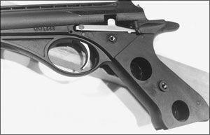
With the plate off, examine the main frame closely. Obvious will be the C-clip (#042) on the hammer pin (#33-4). Less obvious will be the recess for the safety-lock pin (#33-5) under the curve of the action frame. Move your attention to the trigger pin (#037), the sear bar (#021), and the trigger connector (#035). Right in front of
300
the trigger bar there’s a hole in the main frame. Through it, the end of the trigger-spring plunger (#030) can be seen butting up against the sear bar. As you will read later on, that hole plays a significant part in reassembling the Whitney. Finally, locate the magazine-latch pin (#33-3) in the lower rear of the main frame. That is where further disassembly begins.
Press the magazine catch (#031) into the pistol as best you can by pressing the main frame down firmly on your bench top. Maintain pressure while you drift out the latch pin in either direction. The hammer spring (#32-3) will argue with you, but you must take charge of the debate and ease off the down force. This allows the catch, hammer-spring seat (#044), hammer spring, and its plunger (#029) to arrive quietly on your work surface rather than flying freely in any direction they choose. Their absence from the main frame relieves all pressure upon the hammer (#018). Now it’s okay to push part #33-5 up through the action frame and pull out the safety (#050). After you do, note the channel cut in the safety stem. In reassembly, the cut must be aligned with the pin hole in the action frame before the pin can be inserted.
Unless you have a fondness for C-clips, the one attached to the hammer pin will not be looked kindly upon. And I might as well warn you now that you’re going to need two slave pins for reassembly. One is slightly less in diameter than the hammer pin. The other is slightly less in diameter than the sear pin (#33-1). Both must be of a length to ensure they don’t protrude from either side of the action frame. By now you’ve noticed it is no longer as tightly connected to the main frame as it once was.
With the slaves standing by, pop off the C-clip and push the hammer pin out from left to right. Take care not to lose the hammer-pin sleeve (#046) in the process. The magazine disconnect (#043) fits over it. The sear pin drifts in either direction to free up the sear (#019), sear spring (#036), and then the action frame can be pulled from the main frame. This is a perfect time to double check the length of your slave pins.
The trigger pin has a smaller diameter at one end and must be pushed out right to left. A cup-pin punch is recommended. The trigger connector can be pulled out now to separate the trigger from the sear bar. Lift the bar out from the left side of the main frame, take the trigger down through the guard, and remove the trigger-spring plunger and spring from their recess in the main frame—if they don’t fall out on their own.
There’s nothing else to take out, but there’s everything to put back together.Reassembly Tips
Rather than nagging you about taking a mental picture of how the Whitney internal parts fit together as you disassemble it, I’m relying this time on your natural tendency to do exactly that while taking down any firearm.
Tip #1. When you reinstall the trigger plunger over its spring, compress the spring with the plunger and insert a pin or small Allen wrench in that main frame hole already called to your attention to restrain the plunger assembly. Install the trigger and trigger pin, the sear bar, and the trigger connector; pull the trigger to the rear and remove the restraining pin. The plunger will snap into contact with the sear bar.
Tip #2. Your slave pins come into play rebuilding the action frame. Preassemble the hammer, bushing, and magazine disconnector with the disconnector over the bushing. Slip them into the action frame and install your hammer slave pin.
Tip #3. Position the sear spring, straight leg upwards, on the sear. Insert both into the action frame and install the sear slave pin. The straight leg is then moved into the notch on the magazine-disconnector tab to tension the spring. The bent leg of the spring catches under the forward edge of the sear.
Tip #4. Slide the action frame into the main frame, push out the slaves with the original pins, and pop the C-clip back on the hammer pin.
Tip #5. Reach into the main frame with a small screwdriver. Lift up on the magazine disconnector so it catches under the sear bar. Return the hammer to its fired position.
Tip #6. Preassemble the entire magazine catch assembly. Insert it into the main frame. Use a Model 1911 firing pin in the hole of the catch pin to help you line up the magazine catch and install the pin. This is the toughest part of reassembly. You’ll have to press and hold down hard to move the catch into the main frame. If you find it necessary to use a vise, remember you’re dealing with an aluminum frame.
Tip #7. Cock the hammer. Reinstall the safety and capture it in the action frame by pressing the lock pin in from the top. Replace the sideplate and grips.
Tip #8. Turn the cocking piece fully into the breech block and past its alignment slot for the firing pin. Back it off to align with the slot. You install the firing pin and its locking piece after reinstalling the breech pin.
Tip #9. At the upper muzzle end, be absolutely certain the barrel seat is on the barrel inside the main frame and not outside under the barrel nut. Do otherwise and you will have created a headspace problem of .090 inches.
There is no reassembly tip for reinstalling the barrel-index pins (#049). They should never be removed from the tube.


